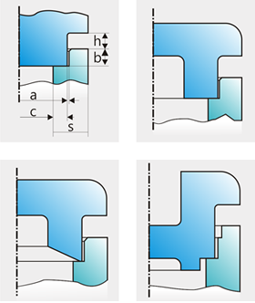
Here are some factors to consider in order to achieve the best results with ultrasonic welding:
The parts should be rigid if the energy must travel some distance to the joint. Softplastics do not transmit the energy well. The walls must be thick enough to prevent deformation of the welding zone. Thin walls tend to break due to mechanical force and ultrasonic exposure during the cycle.
All corners and edges should be radiused if possible. Ultrasonics can cause stress concentrations in sharp inside edges which can cause stress cracks or melting of the material.
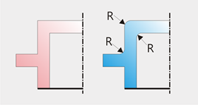
Extended part areas such as ribs, brackets, and studs may break during welding because of vibration and overheating. Inserted components such as springs or wires on electric components are also at risk. lt is best to use generously rounded edges and corners and short welding times at low amplitudes. lf necessary, potting compound such as silicon can be used to dampen the oscillation of electronic components, springs, etc.
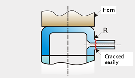
ldeally, one part should mate with the other, and the parts should not be free to slide with respect to each other during the welding process. The fit should be close but not so tight that force must be used to put the parts together before welding. The ideal clearance will fall between 0.05 and 0.1 mm, depending on the size of the parts. The distance that one part should mate into the other should be at least one mm if possible. lf it is not possible to design the parts so that they mate in the weld area, it is also possible to hold the parts in alignment by the fixture or horn.
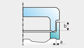
Part design can influence the uniformity of energy delivery to the joint area. For instance, bends, sloping faces and openings in the energy path can reduce the strength of ultrasonic vibrations in the weld area.
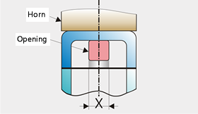
lt is best if the joint area is all in the same plane and the plane of the joint area is parallel to the horn surface. lf the joint area has a step and is not in one plane, the unequal distances from the horn surface may produce uneven welding.
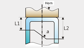
Preferably, the contact surface between the horn and the part should be as large as possible and be flat. Some contouring of the horn surface is often possible. lf the surface of the horn is smaller than the contact area between the parts to be welded, welding may still be accomplished, but some of the energy may not get to the weld area. Also, higher force may be necessary to get a good weld. The higher force may lead to marking of the part surface under the horn.
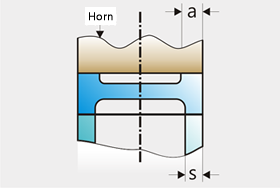
The ideal part construction and design would place the contact surface of the horn as close to the welding area as possible. The term "Near field welding" applies if the distance from the horn to the weld area is 6 mm or less. Applications which permit nearfield welding have the least problems although far field welding can also be very satisfactory if care is used.
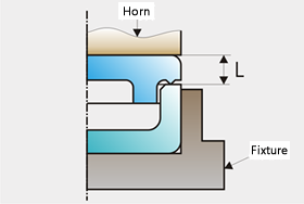
In far field welding, the contact surface of the horn is greater than 6 mm from the welding area. The walls of the upper plastic part transmit the ultrasonic vibrations to the weld area, similar to a transmission line. Rigid, amorphous thermoplastic parts are excellent, low loss ultrasound conductors and best for far field welding. Rigid, semi-crystalline thermoplastics will absorb some energy, making far field welding somewhat more difficult. Soft, semi-crystalline thermoplastics have a high mechanical loss rate. Ultrasonic vibrations are therefore absorbed if the distance between horn and weld area is too great. Welding is difficult and melting of the contact area of the horn is likely to occur.
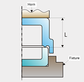
The parts to be welded can be mounted, centered and kept in place by a fixture. The part to be placed in the fixture should be close fitting, not tight and not loose. If the fit is too tight, energy will be lost to the fixture and welding will be difficult. lf the walls of the parts to be welded are thin and not strong enough to support the force of the horn, the side walls may be supported in the welding zone with a temporary insert.
The Energy Director is a V-shaped elevation on one of the two contact surfaces. It causes a line contact as the ultrasonic vibrations begin to melt the plastic. The line contact focuses the ultrasonic energy. As the melt progresses, the energy director turns fluid and flows to fill the space between the two parts. The downward force of the horn causes the melted material to spread over the entire contact surface. At this moment, the ultrasonic energy supply is shut off and the joint area, still under pressure, cools down in a short period of time, completing the weld.
Amorphous thermoplastics do not have a well defined melting point but have a relatively wide softening range. Therefore, welding parameters are less critical and there is reduced chance for thermal damage if the ultrasonic energy is on longer than necessary to obtain a good weld.
Semi-crystalline thermoplastics, on the other hand, have a clearly defined melting point. Most of these materials are sensitive to heat at temperatures above their melting point. Even short times at higher temperatures may cause thermal damage. There is air contact with molten plastic when the energy director is melting and spreading sideways; therefore, the material can crystallize before there is enough heat to weld the entire surface of the joint. Crystallized zones can crack and flake off from the welding area. The air contact may also cause oxidation of the plastic resin. Due to these possible problems, energy directors are not suggested for semi-crystalline materials.
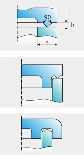
Shear joints are good for achieving a hermetic seal and for semi-crystalline thermoplastics in general. A shear joint is obtained with a step and little contact surface. The small surface and the resulting high energy flow cause rapid melting. The two parts slide into each other, forming a vertical weld joint. The sliding of the two melting surfaces prevents bubbles and limits air contact. The weld is homogenous and usually free of leaks. The regular and even welding procedure is easy to control. Since there is little air contact, cooling is slower and crystallization and flaking of the material is impossible.
The integrity of a shear weld is influenced by the amount of overlap of the two parts. The walls of the lower part must be supported in the welding
zone to prevent bulging due to welding pressure, especially if the walls are thin.
