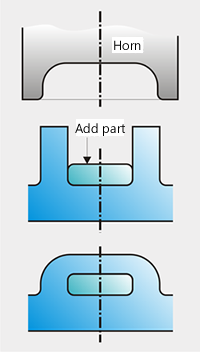
In addition to traditional ultrasonic welding, fusion forming by means of ultrasonic offers a very wide range of possible applications:
These processes considerably extend the use of ultrasonic. They offer the possibility of formlocked combining of thermoplastic synthetics with other materials – metals, glass or dissimilar plastics. Unlike welding, in the case of fusion forming only one plastic part is locally plasticized and shaped in its viscous state. In this way effective use is made of the heat energy between the horn surface and the surface of the plastic part.
Forming by ultrasonic has important advantages over other techniques. Because the forming takes place in the melting phase, only negligible stresses arise in the shaped parts – provided the machinery is correctly adjusted. The problem of stress relaxation is practically non-existent. Fixed connections with no play in them are achieved, coming up to very exacting demands, even in their longterm behaviour.
The horn transfers the mechanical oscillation energy to the rivet spigot. It is the riveting tool while at the same time being worked on the face side to the desired rivet headshape. This recess corresponds to the volume of the shaped plastic. Particular attention must be paid to the wear on horn tips, especially when working with abrasive materials. Plastics with mineral fillers or glass fibres require the use of suitable horn materials. Hardened tool steels of hardnesses above 60 HRc, or a suitable coating are recommended.
Thin metal parts can be excited by ultrasonic vibrations and there is a tendency for the parts to climb up against the horn. A clean bond is not guaranteed. Clamping down devices will help. The vibrations can also lead to the break up of exposed parts. Such problems are solved by using sound-compensating materials, possibly combined with clamps designed for the purpose.
lf metal parts are fixed with several rivet heads, all rivet heads should be shaped in one working cycle. lf rivet joints are made individually, the sound energy is conducted through the metal part to the already shaped rivet heads and can lead to breakage.
The horn must not touch the part to be attached. The plasticized material must solidify under pressure during the cooling time. This procedure can be compared with the stress and cooling time for injection moulding. lf the horn lies on the upper part, the pressure on the rivet head is reduced. The result is a non-homogeneous structure with resultant loss of strength.
When metal parts are being riveted, this problem is solved very neatly in the form of a contact breaker. A suitably equipped absorption tool, connected electrically to the controls, causes cut off of the ultrasonic energy if the horn touches the metal part. A welcome secondary phenomenon with this system is that component tolerances are automatically compensated for.
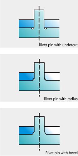
The general shape of a rivet joint is known from the machine construction. The fixing of the rivet pin should in all circumstances be provided with a ringshaped undercut, with a radius or at least with a bevel. In either case the part to be riveted on must of course be recessed.
The same applies to the upper edge of the hole of the part being riveted on. lf cost considerations and manufacturing capabilities allow, a radius or at least a bevel should be made here. These measures prevent notch effect and stress concentrations, which can lead to breakages even when shaping the rivet head.
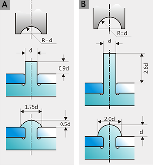
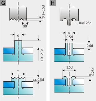
The simplest head shape, as in illustrations A and B, is used chiefly for rivet pins up to approx. d = 4 mm. Partically crystalline thermoplastics can in certain circumstances be difficult to work in these forms, because no particular care is taken over melting of the material. A proven, modified shape helps here. The horn has a central tip. The ultrasonic energy is thereby heavily concentrated and greatly assists melting of the material. As a result short welding times and good strength values are achieved.
Head shape E shows an alternative to the central spike. Here melting of the material is assisted by suitable shaping of the spigot. lt is important for this tip to be sharp-edged or shaped with a maximum radius of 0.2 mm. This shape is favourable for working with glass fibre reinforced materials.
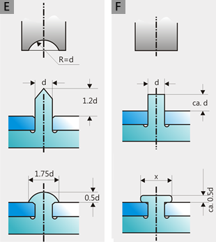
Head shapes F and G are not defined, these applications are limited to places which are not visible on the finished product.
For partially crystalline thermoplastics and larger spigots, steps must be taken to assist with the melting. A rhombic shaping (Kourl pattern) of the horns has proved very successful. Quite understandably, these two variants do not meet any special requirements for strength. They are used in preference for the fixing of metal parts in electrical engineering.
For the larger spigot diameters, from about 6 mm upwards, the use of hollow spigots as in illustration H is recommended. Accumulations of material and therefore sink marks on injection moulded parts can thus be avoided. The quantity of material to be shaped is reduced, which is beneficial in terms of the welding time and the energy requirement.
The suggested standardization represents approximate values. These can of course be varied and adapted to individualrequirements.
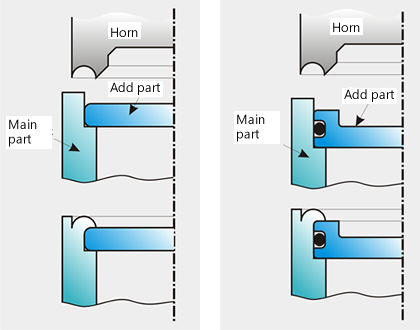
The flanging technique is known from metal-working. The most important characteristic in the case of ultrasonic flanging is that the material is plasticized by the ultrasonic energy and shaped in the viscous melting phase.
A typical application is shown as picture. The designer has a relatively free choice in shaping jointed flange connections, though the parts being shaped must exceed the volume calculation.
Even if such joints meet very high specifications, they can never be airtight because of the unequal thermal expansion of both parts. lf airtightness is essential, a separate sealing element must be inserted. The other pictures shows an airtight flanging joint where an 0-ring is used.
When soft materials are being welded, unacceptable welding ridges often occur. Here flanging offers an alternative to traditional welding.
Ultrasonic embedding is a very efficient but little used method of joining different form-locking parts to each other. Wall thicknesses and ribs on the synthetic part are plasticized by the horn and pressed into recesses, undercuts and holes. In this way electrical contact elements, for example, can be bedded into plastic housings, plastic parts can be fixed radially and axially on to steel shafts etc.
